Christian_Bylund wrote: ↑12 Jan 2021 18:22
Hi DonP,
DonP wrote: ↑12 Jan 2021 10:24
Not intending to highjack this thread, but when reading through the task list it came to my mind that maybe some basic software interface to adjust these values would very much lower the entry level:
- Knock sensor measurement timing.
- Knock sensor amplification and gain.
- Knock sensor frequency filtering.
Maybe even displaying the result?
You might be right, how about a Knock Shield App for Windows / iOS / Android?
Hi Christian,
How are you,
Firstly apologies to the original poster for stepping in on your post also.
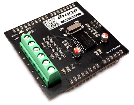
I still have to purchase my KNOCK SHIELD from you to add to my WIDEBAND SHIELD.
However, now discovering Knock Shield 2 is underway i shall wait.
With the extra ideas brought up throughout this topic, will your current planned Knock Shield 2 require physical changes to the PCB or hardware installed to the board, like with regards to the display, etc?
Should i hold off on my purchase to get SERIES 2 or will it be fine to purchase and the rest of the upgrades are easily added on?
I have also read some more of this topic and see that some of my questions/ideas are already addressed, apologies to all for jumping the gun before reading the topic entirely.
The mention of some software sounds like an excellent addition to your quality product, with your mention of displaying the result, sweet an LCD. Displaying the knock level, or intensity with a bar graph for example, and accompanied by a numeral-based equivalent.
So a full bar graph = 100 (numeral figure) for example, showing that the detonation is at maximum level and severe engine damage is inevitable.
Any chance of having a 0 - 5 volt DC analogue output that we can use with an ECU, for data logging also.
Each volt is equal to a knock level of 20 on the KNOCK SHIELDS DISPLAY and would be also used in creating a calibration file for the ECU you wish to use.
So,
0.00 volts = 0
0.25 volts = 5
0.50 volts = 10
0.75 volts = 15
1.00 volts = 20
1.25 volts = 25
1.50 volts = 30
1.75 volts = 35
2.00 volts = 40
2.50 volts = 50
3.00 volts = 60
4.00 volts = 80
5.00 volts = 100 max detonation.
Then selecting a level that equates to ignored noise and another level that equates to true detonation, which will be derived by the software and the frequency required to suit the bore diameter etc.
For example, anything reading from 0 to 35 - 40 is engine noise, anything above this is deemed light detonation through to full detonation.
If you notice i have dropped the 0.25-volt scale off from 2.00 v/DET LVL 40 through to 5.00 v /DET LVL 100 as i believe the 0.25 v increments won't be required up at that level but also it should stop the data from being too sensitive up at those levels causing data reading bounce.
So i don't know if this is any good to you Christian, hopefully, it may be of use when writing the algorithm for it.
Just an idea.
Take care mate,
Regards
Dave.
