Page 1 of 1
10 bit ADC voltage conversion
Posted: 25 Sep 2020 14:53
by HeinrichG
Hello Christian,
first of all, you did really nice job by the development of the both lambda shields :)
At the moment I'm developing a own lambda controller for LSU4.9 probe. The aim of this is to replace the narrow band sensor in my car. On this way I found your project.
In the technical manual of lambda shield 2, on page 5 in chapter 4.1 you calculate Ua with this equation:
Ua = ADC / 1023 * 5.0
Why 1023? The ADC range is going from 0 to 1023, but you have got 1024 values, because of 10-bit ADC.
The equation in Atmega datasheet looks like:
ADC = Vi * 1024 / Vref or resolved to Vi:
Vi = ADC / 1024 * Vref (Vi = Ua, Vref = 5.0V)
In the example code you always calculate with 1023, not 1024.
I think, it is not correct. Or am I wrong?
Re: Is that really correct?
Posted: 25 Sep 2020 20:40
by kevin
Like you said;10bits...
Do the math the difference is nearly nothing, a couple of microvolts.
5/1024 = 4.883mV
5/1023 = 4.888mV
Re: 10 bit ADC voltage conversion
Posted: 25 Sep 2020 22:27
by Christian_Bylund
Hello Henrich,
Thank you for the positive feedback. If you need a reference design you know where to order it!
Regarding the classic 1023 vs 1024 discussion.
The ADC is 10 bits (1111111111) corresponding to the highest value of 1023, it is still 1024 values counting the 0 value. But the highest value represented is 1023.
If the ADC reference is 5V and the ADC input is 5V we can agree that ADC should fill the 10 bits i.e 1023. You can try this on your Arduino, the largest value you will get is 1023.
You can also read about the returns in the Arduino Reference.
So using 1024 will convert 5V input (with 5V ADC reference) to 1023 / 1024 * 5.0 = 4.99V.
I'll leave it to you to decide if you want to use 1023 or 1024. But as Kevin has already pointed out, it doesn't really matter.
Re: 10 bit ADC voltage conversion
Posted: 27 Sep 2020 14:23
by HeinrichG
Hello Christian,
thank you :) I need this as "standalone controller" for my car. In my project I'm using Bosch LSU 4.9 probe (0 258 017 025, during the development an 1:1 replacement, so not the original one, till the heater controll is done and tested), CJ125 in TQFP32 package, an Atmega324PB MCU, Infineon TLE42754D voltage regulator with reset controler. All the ICs are automotive grade and I use 4-layer PCB. If you want, I can provide you the schematic and BOM.
All what yoi write is absolutely correct. In the equation you need the possible value count (10-bit = 1024 or 8-bit = 256, depends on configuration of ADC resp ADLAR-bit in ADMUX register) and NOT the maximum value, check the datasheet of i.e. Atmega2560, Page 280: ADC = Vin * 1024 / Vref.
I am not talking about the deviation or precision, but about the fact that the equation is not correct at all. It has no great effect now, that is correct. Because, it is just 0.0048V, as you say.
No offense and regards :)
Re: 10 bit ADC voltage conversion
Posted: 27 Sep 2020 16:37
by Christian_Bylund
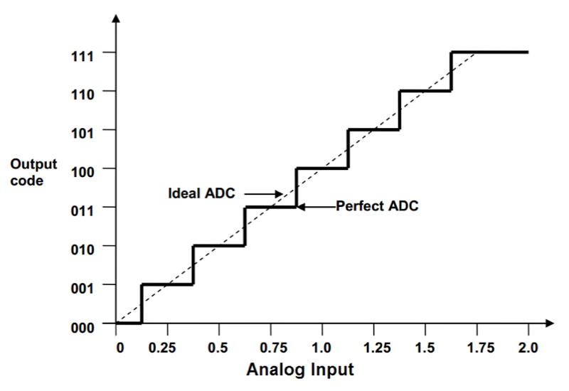
 Above is the section in the data sheet for everyones reference. Note that 0x3FF (1023) does not represent VREF but VREF - 1 LSB.
 Above highlights this with the 3-bit ADC example which in the above example outputs 7 (111) for both 1.75V and 2.0V input.
HeinrichG wrote: ↑27 Sep 2020 14:23
I am not talking about the deviation or precision, but about the fact that the equation is not correct at all.
You are right that using 1024 is correct because 1023 does not represent VREF but VREF - 1 LSB (1 LSB = VREF / 1024).
I shall update the code and technical manuals when appropriate.

