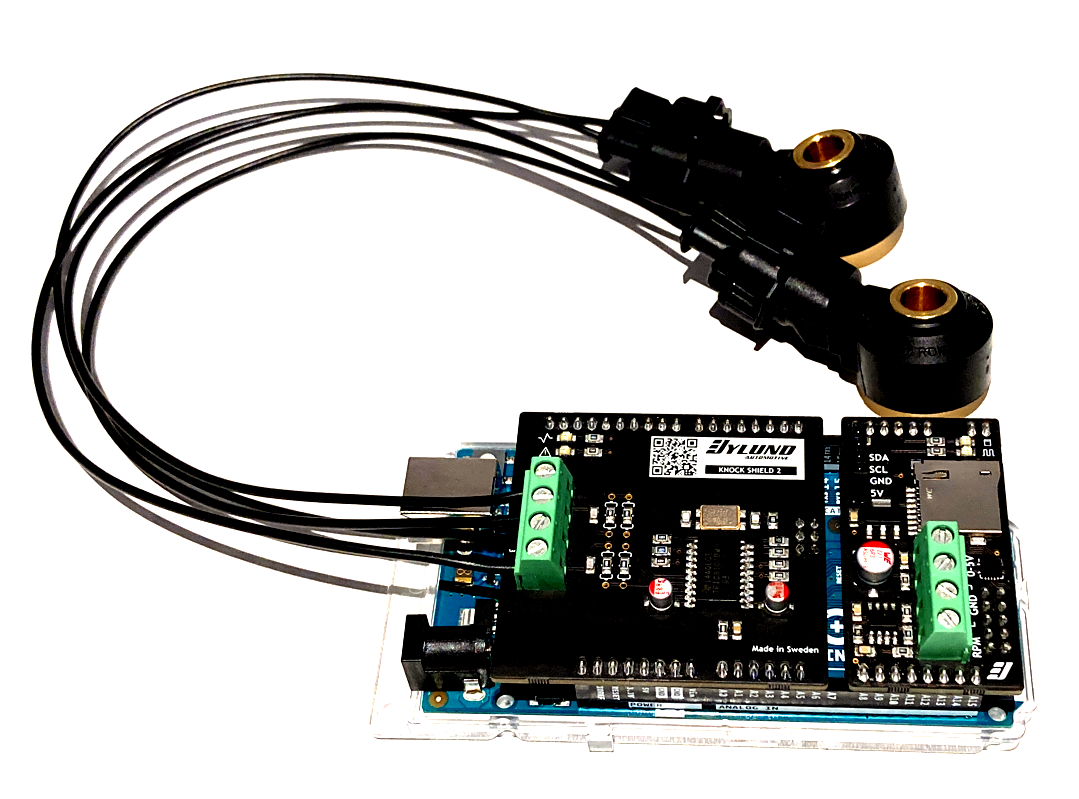
Just out of curisosity:
What purpose will the two additional resistors R10 and R11 on pins 7 and 14 serve?
Thank you.
PS: will the add-on board as can be seen next to the new Knock Shield 2 (http://www.bylund-automotive.com/educat ... _Promo.png) be available for both the knock shield and the lambda shield?
Knock Shield 2
Re: Knock Shield 2
One more question: if I used the Knock Schield 2 (which seems to come without the headers) on a basic Arduino Uno or Uno WiFi, would I still be able to feed a tach signal to the shield or Uno? Or will I have to resort to the soldering iron? Many thanks!
- Christian_Bylund
- Posts: 270
- Joined: 07 Mar 2015 18:09
Re: Knock Shield 2
Hello DonP,
Thank you for the positive feedback.
I hope it answers your questions.
Thank you for the positive feedback.
R10 and R11 are just pull-down resistors for the HOLD and TEST pins. I added them for good design practice in the new revision.
Yes, the expansion shields will be compatible with Knock Shield 2, Lambda Shield 2 and NOx Shield.
Unfortunately you need to resort to soldering for the UNO's.
I hope it answers your questions.
Best Regards,
Christian Bylund
Bylund Automotive AB
Christian Bylund
Bylund Automotive AB
Re: Knock Shield 2
Hi Folks, I'm a bit of a newbie to this, however it does seem that a tach input and rpm scaling would be very useful. So given that the Shield masks or even plugs into the headers (not sure) what soldering is required, could anyone elaborate? thanks.
Re: Knock Shield 2
According to the source code of the Knock Shield Interrupt Example, it should be pin 2:
"#define TACH_INPUT_PIN 2 /* Pin used for tach signal from ECU. */"
https://github.com/Bylund/Knock-Shield- ... pt-Example
A very good intro by Christian can be found here:
https://youtu.be/47qFX65oJoo
"#define TACH_INPUT_PIN 2 /* Pin used for tach signal from ECU. */"
https://github.com/Bylund/Knock-Shield- ... pt-Example
A very good intro by Christian can be found here:
https://youtu.be/47qFX65oJoo
Re: Knock Shield 2
Thank you Don for your reply. I have studied the video and all the documentation. I have also found some other videos on YouTube that solder Arduino header pins. Whilst this is not my first use of Arduino, having implemented previously a fuel pressure and fuel temperature gauge, I still feel that soldering header pins is a potentially dangerous activity, given the consequences of engine knock. There seem to be 4 physical inputs to the Knock shield, why couldn't the factory offer a fifth, given the benefits of monitoring RPM for both data logging and rpm scaling? So this is not a good way to start as far as I am concerned. A better way to start, IMHO, is monitor knock in stages, say 2k - 3k rpm, then 3k - 4k rpm and so on, and match the gain constant to each band. I think I will also be tempted to run the "Det Can" (headphone/microphone) approach in parallel to build confidence in the system. Thoughts welcome. Thanks.
Re: Knock Shield 2
Correction to my last post. Gain constant (Ap) is a calculated value. Integrator time constant is the one that could be usefully varied with engine speed.
- Christian_Bylund
- Posts: 270
- Joined: 07 Mar 2015 18:09
Re: Knock Shield 2
Hello K6EcuUser,

The idea is that you use Arduino Mega 2560 if you want to connect hardware or signals.

Absolutely correct.
Best Regards,
Christian Bylund
Bylund Automotive AB
Christian Bylund
Bylund Automotive AB