Page 1 of 1
Please explain the thing
Posted: 02 Jan 2021 12:50
by DizTheFiddler
Hi,
i dont really get the idea behind this. Could you please answer a few questions?
- When does this integration window start and when does it end and what is it for?
- is the value thats integrated (the gradient of the integration) depending on the sound level thats heard by the sensor?
- what does the arduino do with the analog voltage thats given by the knock shield?
Could you please explain how it is intended to work and how i can use it as an input to my ECU. Whats the idea behind this?
Thanks
Diz
Re: Please explain the thing
Posted: 04 Jan 2021 02:13
by Christian_Bylund
Hi Diz,
DizTheFiddler wrote: ↑02 Jan 2021 12:50
Could you please explain how it is intended to work and how i can use it as an input to my ECU. Whats the idea behind this?
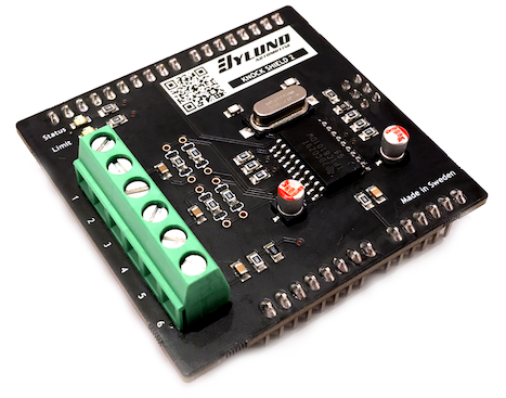
The Knock Shield for Arduino is a reference design of the most common Knock IC's - Texas Instruments TPIC8101DW and Renesas / Intersil HIP9011. It can be used to design your own knock circuit or as a highly configurable knock sensor kit.
DizTheFiddler wrote: ↑02 Jan 2021 12:50
When does this integration window start and when does it end and what is it for?
By your question I assume that you have already read the
Technical Manual. The integration window is when the sensor is measuring, typically triggered by the position of the crankshaft in relation to ignition timing.
DizTheFiddler wrote: ↑02 Jan 2021 12:50
Is the value thats integrated (the gradient of the integration) depending on the sound level thats heard by the sensor?
What does the arduino do with the analog voltage thats given by the knock shield?
The integrated value is the accumulated sound matching the high- and low-pass filters. The Knock Shield is basically a Digital Signal Processor (DSP) only listening to a certain frequency. After each measurement (time window) the shield outputs an analog signal 0-5V (0-100%) for the Arduino to read.
If you haven't already, watch our explanatory
DIY video of the Knock Shield for Arduino on YouTube.
Hope it helps!
Re: Please explain the thing
Posted: 04 Feb 2021 11:02
by DizTheFiddler
Thank you very much for the infos. But of course i have some more questions. ;)
- How does the crank position signal have to look like and which voltage level is allowed? Im running a rotating distributor with a magnetic pickup. My ingition box puts out a rectangle signal for the tach, so i could use the symmetric sinus of the magnetic pickup or a 0-14V rect signal (or splitted to 0-5V if needed) to start the window.
- Can knock shield start the window before the rpm signal indicates TDC (or slightly off) of each cyl or only a few degrees after?
- I guess i can use a Arduino Tiny Every for reading the 0-5V signal of the chip too, if i can hook the shield up to the power supply and ADC?!
- Is there a manual which covers all these questions?
Thanks a lot!
Dieter
Re: Please explain the thing
Posted: 04 Feb 2021 12:42
by Christian_Bylund
Hi Dieter,
DizTheFiddler wrote: ↑04 Feb 2021 11:02
- Is there a manual which covers all these questions?
The original Knock Shield have no additional hardware for trigger / tach inputs so it is relying on the digital pin of the Arduino which means you need a signal compatible with the microcontroller of the Arduino you are using.
It is no secret that I am working on the updated Knock Shield 2 that will feature signal handling for this input. The first prototype had a simple voltage divider handling 12V inputs. For my next prototype I think I will go for a comparator solution instead, allowing any signal between 3.3V and 24V. What do you think?
DizTheFiddler wrote: ↑04 Feb 2021 11:02
- Can knock shield start the window before the rpm signal indicates TDC (or slightly off) of each cyl or only a few degrees after?
- I guess i can use a Arduino Tiny Every for reading the 0-5V signal of the chip too, if i can hook the shield up to the power supply and ADC?!
I guess this is the benefit of an Arduino based knock monitor compared to an aftermarket / tuning solution. You can interface using the sensors you have available and program it to work the way that is most suitable for what you want it to do.
Hope it answers your questions.
Re: Please explain the thing
Posted: 09 Feb 2021 11:00
by DonP
Christian_Bylund wrote: ↑04 Feb 2021 12:42
It is no secret that I am working on the updated Knock Shield 2 that will feature signal handling for this input. The first prototype had a simple voltage divider handling 12V inputs. For my next prototype I think I will go for a comparator solution instead, allowing any signal between 3.3V and 24V. What do you think?
More of a question not related to a signal coming directly from e.g. the coil: if one is already using an EMS that outputs an angle-angle based 5V knock window, could this be used with this new interface?
Or could I interface this to the Arduino Uno already now? I already have the current Knock Shield, but have too little knowledge of the electronics side...
Thank you!
BR,
Pascal
Re: Please explain the thing
Posted: 10 Feb 2021 11:42
by DonP
DonP wrote: ↑09 Feb 2021 11:00
Or could I interface this to the Arduino Uno already now? I already have the current Knock Shield, ...
Maybe answering my own second question: I suppose an angle-angle based signal would - as per the Youtube video on the interrupt example - just be connected to the TACH_INPUT_PIN (2) and then one could attach a second ISR to the falling edge of this signal.
Re: Please explain the thing
Posted: 10 Feb 2021 13:04
by Christian_Bylund
Hi Pascal,
DonP wrote: ↑10 Feb 2021 11:42
Maybe answering my own second question: I suppose an angle-angle based signal would - as per the Youtube video on the interrupt example - just be connected to the TACH_INPUT_PIN (2) and then one could attach a second ISR to the falling edge of this signal.
Exactly, if the Arduino you are using is happy with the signal it will work. You can configure to trigger on rising or falling edge of any signal.
DonP wrote: ↑09 Feb 2021 11:00
More of a question not related to a signal coming directly from e.g. the coil: if one is already using an EMS that outputs an angle-angle based 5V knock window, could this be used with this new interface?
It should work fine, you can program to measure between triggers or trigger and a certain time or speed configured. As you can see in the manual the DSP have many levels of configuration. The important thing is to find a reference level that is sensitive enough on a safe map.
I suggest you also see how commercial knock sensors are configured on safe maps before starting to rely on the knock output. There are plenty of videos on YouTube.
Good luck!
Re: Please explain the thing
Posted: 16 Feb 2021 21:03
by DizTheFiddler
Thank you very much Christian,
since i design a platine with a arduino nano every for my car anyway, i want to evaluate the 0-5V signal for the Knock Shield with the nano too. Which wires do i need to connect? I guess
- 5V supply
- GND
- 0-5V signal, which is TPIC8101 UA??
Anything else needed?
Regards
Dieter
Re: Please explain the thing
Posted: 21 Feb 2021 08:37
by Christian_Bylund
DizTheFiddler wrote: ↑16 Feb 2021 21:03
Since i design a platine with a arduino nano every for my car anyway, i want to evaluate the 0-5V signal for the Knock Shield with the nano too. Which wires do i need to connect?
I think you should have a look at the
schematics. What is minimum is of course supply and ground. The controller needs to be initialized after power up so you need SPI for that. Last you are going to need the hold pin to set the timing window and the UA to measure the output.
Good luck!