Page 1 of 2
Lambda Shield 2 installation
Posted: 21 Jun 2020 11:11
by wolf
Hello Christian,
first of all, great work..
I have a few questions:
1: is it possible, to use an external power source for the heater, for example, direct from the battery of a car and the shield and arduino from an regulated power source?
2: is it possible, to remove the serial outputs, without affecting the function of the lambda shield or arduino?
Greetz from Germany
wolf
Re: lambdaShield2 sketch & hardware
Posted: 21 Jun 2020 16:52
by Christian_Bylund
Hello Wolf and thank you!
wolf wrote: ↑21 Jun 2020 11:11
1: is it possible, to use an external power source for the heater, for example, direct from the battery of a car and the shield and arduino from an regulated power source?
I assume you are referring to your Lambda Shield 2, this is described in the
Technical Manual, 3.2 – Alternative Power Input. With the X7 Jumper enabled you can power the Arduino from same power source as the heater using the built in 5V regulator. Watch
this video for more information.
Just make sure you never power both the Arduino DC-jack and the Lambda Shield DC-jack with X7 enabled. Only the Lambda Shield.
wolf wrote: ↑21 Jun 2020 11:11
2: is it possible, to remove the serial outputs, without affecting the function of the lambda shield or arduino?
Serial output is not necessary for the function, on the other hand it is quite useful for debugging. But you do not need any USB connected.
Re: lambdaShield2 sketch & hardware
Posted: 21 Jun 2020 17:18
by wolf
hi Chrstian,
thanks for your reply.
To use an other power supply I thought about connecting Pin X6-4 direct with the 12-volt vehicle electrical system, cause the regulated power supply for the Arduino and LambaShield is connected over a 150µH inductance (+ a bidirectional ZVS-Diode between + and -) to the 12-volt vehicle electrical system (the inductance is only for 1,2Amps)
Re: lambdaShield2 sketch & hardware
Posted: 22 Jun 2020 22:47
by Christian_Bylund
wolf wrote: ↑21 Jun 2020 17:18
To use an other power supply I thought about connecting Pin X6-4 direct with the 12-volt vehicle electrical system, cause the regulated power supply for the Arduino and LambaShield is connected over a 150µH inductance (+ a bidirectional ZVS-Diode between + and -) to the 12-volt vehicle electrical system (the inductance is only for 1,2Amps)
Hi Wolf, bare in mind the Ubat input on the CJ125. That being said, I am always for a good
Muntzing practice!
Re: lambdaShield2 sketch & hardware
Posted: 27 Jun 2020 00:54
by wolf
Shield and power supply in the box...
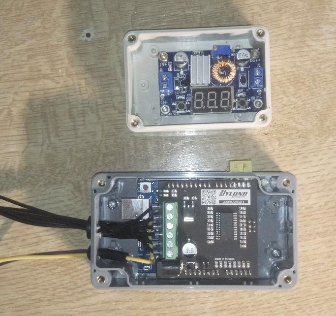
if 'img' doesn't function:
https://ibb.co/vd90fTm
Re: lambdaShield2 sketch & hardware
Posted: 27 Jun 2020 11:38
by Christian_Bylund
wolf wrote: ↑27 Jun 2020 00:54
Shield and power supply in the box...
Nicely done!
Is the power supply for when you are not using it in the vehicle? Both the shield and the Arduino can be powered by the vehicles 12V (14.4V).
Re: lambdaShield2 sketch & hardware
Posted: 27 Jun 2020 15:32
by wolf
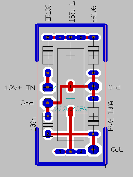
The power supply (a DC/DC Converter (5A)) in combination with a little PCB (30x13mm) is used to
supress transients
The shield will be installed in my YFM660R Raptor and later in my Corsa B.
I used a schematic from VW for a T4-Bus for supression of transients.
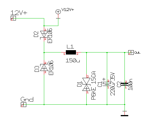
(D2 is obsolet..)
Greetz
wolf
Re: lambdaShield2 sketch & hardware
Posted: 27 Jun 2020 23:24
by Christian_Bylund
wolf wrote: ↑27 Jun 2020 15:32
The power supply (a DC/DC Converter (5A)) in combination with a little PCB (30x13mm) is used to
supress transients
The shield will be installed in my YFM660R Raptor and later in my Corsa B.
I used a schematic from VW for a T4-Bus for supression of transients.
Greetz
wolf
Thank you for sharing if anyone runs in to trouble. Please share your results in the Raptor and Corsa.
Have you considered using the Uno WiFi and the Lambda Shield App?
Re: lambdaShield2 sketch & hardware
Posted: 28 Jun 2020 02:08
by wolf
i don't possess a smartphone... ;-)))
For a permanent installation I would prefer an Arduino Mega Mini and a little TFT Touchscreen display, perhaps coneccted with stackable headers, otherwise with 14 lines from Arduino to TFT... like this one:
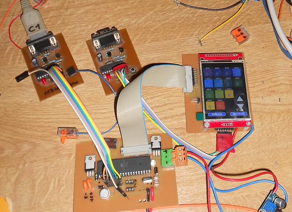
(was a project for a quickshifter with ajustable interrupts in ms for the ignition)
in a car with binary Lambda sensors I will probably only get values around Lambda=1 ( if not being able to fake the signal or voltage from these sensors)
For the Yamaha quad I use an AFR-Gauge with 0-1V.
reports follow, as soon I get the threaded sleeve for the lambda sensor from the USA.
Greetz from Laupheim, Germany
wolf
Re: Lambda Shield 2 installation
Posted: 30 Jun 2020 22:52
by DaveK
Hi Wolf,
that's a very nice little kit you have assembled there, very well done, looks great.
Regards
Dave.